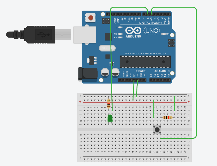
CIRCUIT 1 - PUSHBUTTON AND LED (DIGITAL INPUT, DIGITAL OUTPUT)
Electronics - Build a real circuit as the one shown below:
Programming:
Set up variables:
int led = 6;
int button = 5;
Then comes the setup function. (LED is an output device. Pushbutton is an input device.) We use the keyword pinMode to specify input/output.
void setup() {
pinMode(led, OUTPUT);
pinMode(button, INPUT);
}
Finally, we complete the main loop function. If button is pressed, it reads HIGH on pin 5, and we write HIGH on pin 6 to light up the LED.
void loop(){
bool button_pressed = digitalRead(button);

if (button_pressed == HIGH){
  digitalWrite(led, HIGH);
}

else if (button_pressed == LOW){
  digitalWrite(led, LOW);
}
}
Once you have the whole code properly set up, upload it to your Arduino. Connect your Arduino to the circuit and it should be “smart” – the LED should light up when you press the button.
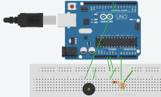
Circuit 2 - Photoresistor and Buzzer (ANALOG INPUT, VARIABLE OUTPUT)
Electronics - Once again, build a real circuit as the one shown below:
Programming:
As earlier, we set up variables:
#define photoresistor A0
int buzzer = 7;
Then we specify INPUT/OUTPUT pinmodes in the Setup function. Photoresistor is used as a sensor i.e. input; buzzer is used as a speaker i.e. output.
void setup() {
Serial.begin(9600);
pinMode(photoresistor, INPUT);
pinMode(buzzer, OUTPUT);
}
Finally, we make the real action happen inside the loop function:
void loop() {
int sensor_value = analogRead(photoresistor); //read sensor value and store it into the integer sensor_value
int buzzer_frequency = map(sensor_value, 1023, 0, 31, 2000); // Map the sensor values to the buzzer frequency (1023 - 0 to 31 - 4000)
tone(buzzer, buzzer_frequency); //play the buzzer depending on the sensor values
Serial.println(sensor_value);
}
Once you upload the whole code to the Arduino board and setup the complete circuit, try shining light onto the photoresistor; the buzzer should beep at varying frequencies.
CIRCUIT 3 - MAKING THINGS MOVE (SERVO MOTORS - ANALOG OUTPUT)
Now let’s do something more interesting and control servos!
Servos are Positional devices: they move an output arm to different positions as commanded by a signal. This signal will be provided by an Arduino! Servos come in different shapes and sizes. Here is the servo that we will be using:

Servos have a three wire connector. One wire supplies positive DC voltage – usually 5 to 6 volts. The second wire is for ground, and the third wire is the signal wire. The Arduino “talks” to the servo through this wire by means of a simple on/off pulsed signal. They can plug directly into the 3-pin connectors on your Arduino.
CONNECTIONS:
- Servo Brown to Ground
- Servo Red (Center wire) to +5V
- Servo Orange to Signal (Pin 11)
And here’s a basic code to control the servo. Don’t get scared by the length of the code - it mostly includes comments to clarify any misunderstandings!
/* YourDuino Basic Robot Kit V2: Test Servo movement
 - WHAT IT DOES: Tests the servo by commanding it to go to several different directions
   to "Look Around".

/*-----( Import needed libraries )-----*/
#include <Servo.h>

/*-----( Declare Constants and Pin Numbers )-----*/
#define SERVO_PIN 11 // Servo plugs into Pin 11

/*-----( Declare objects )-----*/
Servo myservo;  // create servo object to control a servo

/*-----( Declare Variables )-----*/
int pos;    // variable to store the servo position

void setup()   /****** SETUP: RUNS ONCE ******/
{
  myservo.attach(SERVO_PIN);  // attaches the servo on pin 11 to the servo object

}//--(end setup )---

void loop()   /****** LOOP: RUNS CONSTANTLY ******/
{
  for(pos = 20; pos < 160; pos += 30)  // goes from 0 degrees to 180 degrees
  {                                  // in steps of 30 degree
    myservo.write(pos);              // tell servo to go to position in variable 'pos'
    delay(1000);                      // Wait 500ms between pings
  }

  for(pos = 160; pos>=20; pos -= 30)     // goes from 180 degrees to 0 degrees
  {
    myservo.write(pos);              // tell servo to go to position in variable 'pos'
    delay(1000);
  }

}//--(end main loop )---

/*-----( Declare User-written Functions )-----*/
//NONE

//*********( THE END )***********
CIRCUIT 4 - ULTRASONIC SENSOR AND LEDs
This is very similar to circuit 2 - sensing an input, processing it, and producing output. Build a circuit as shown below:

First we define some variables so that it’s easy to refer to the sensor, LED, and buzzer pins in the code.
#define trigPin 7
#define echoPin 6

#define led 13
#define led2 12
#define led3 11
#define led4 10
#define led5 9
#define led6 8

#define buzzer 3

int sound = 250;
Next up, we need to setup the pinModes for each device in the setup function. We do that by using the pinMode keyword as we have already seen a couple times already.
void setup() {
  Serial.begin (9600); // So that we can communicate with the circuit and read the sensor values

  pinMode(trigPin, OUTPUT);
  pinMode(echoPin, INPUT);

  pinMode(led, OUTPUT);
  pinMode(led2, OUTPUT);
  pinMode(led3, OUTPUT);
  pinMode(led4, OUTPUT);
  pinMode(led5, OUTPUT);
  pinMode(led6, OUTPUT);

  pinMode(buzzer, OUTPUT);

}
Then, we code the details of our circuit in the main function. The basic idea is: the closer our hands are to the sensor, the louder the buzzer sounds. Also, the LEDs begin to light up in progressive fashion.
Since this code is a little bit complicated, try to understand how it works first, and then copy-paste it to your IDE.
void loop() {
  long duration, distance;
  digitalWrite(trigPin, LOW);
  delayMicroseconds(2);
  digitalWrite(trigPin, HIGH);
  delayMicroseconds(10);
  digitalWrite(trigPin, LOW);
  duration = pulseIn(echoPin, HIGH);
  distance = (duration/2) / 29.1;

  if (distance <= 30) {
    digitalWrite(led, HIGH);
    sound = 250;
}
  else {
    digitalWrite(led,LOW);
  }
  if (distance < 25) {
      digitalWrite(led2, HIGH);
      sound = 260;
}
  else {
      digitalWrite(led2, LOW);
  }
  if (distance < 20) {
      digitalWrite(led3, HIGH);
      sound = 270;
}
  else {
    digitalWrite(led3, LOW);
  }
  if (distance < 15) {
    digitalWrite(led4, HIGH);
    sound = 280;
}
  else {
    digitalWrite(led4,LOW);
  }
  if (distance < 10) {
    digitalWrite(led5, HIGH);
    sound = 290;
}
  else {
    digitalWrite(led5,LOW);
  }
  if (distance < 5) {
    digitalWrite(led6, HIGH);
    sound = 300;
}
  else {
    digitalWrite(led6,LOW);
  }

  if (distance > 30 || distance <= 0){
    Serial.println("Out of range");
    noTone(buzzer);
  }
  else {
    Serial.print(distance);
    Serial.println(" cm");
    tone(buzzer, sound);

  }
  delay(500);
}